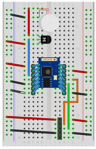
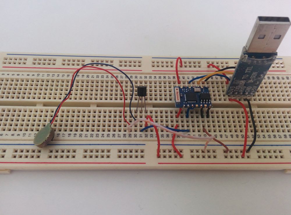
Now its time to wire up the programming circuit.
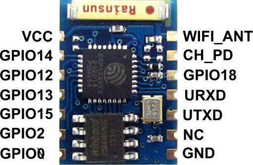
These are the pinouts for the ESP8266-03.

- VCC is power.
- GND is ground.
- CH_PD is connected to power.
- URXD goes to TX on the USB to Serial adapter.
- UTXD goes to RX on the USB to Serial adapter.
- GPIO0 is tied low (to ground) when programming.
- GPIO12 goes to the transistor which powers the vibration motor.
- GPIO15 always goes to ground.

After the code has been flashed a lot of these wires can be removed, simplifying the final product.
Don't worry if it looks a little complicated, following each wire one at a time makes placing them all down very easy.
This is what is needed to program the ESP8266.

When everything is wired up, it's time to flash the code.
